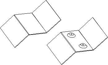
Creo Sheet Metal Lance

Conversion feature is used for edge rips and rip connects.
Creo sheet metal lance. Just convert the imported 3d model into a creo sheet metal part by defining a driving surface and you re ready to go. For this part i would use double shell method. First shell thickness defines flange size. What happened to this functionality.
If the reference model has a coordinate system component interface configured you can quickly place a die form reference part as an on surface coordinate system or by using component interfaces. 925 423 7496 lawrence livermore national lab 7000 e. In the creation. Convert a part to sheet metal.
In this tutorial we will learn about the basic techniques related to sheet metal functionality of creo parametric by modelling a cover. The die form workflows and user interface have been enhanced and modernized in ptc creo 3 0 so they are consistent with those of the punch form tool. Using a variety of y and k factor bend allowance calculations designers can create flat patterns of the designs. See convert a solid part into a sheet metal part for details.
When creating flat wall you have at corner of the bend line a white box which can be used for extending and. I don t use sheetmetal mode often i m trying to add a hem to a part and i don t find anything in the creo 2 update training on it search for hem in creo turns up nothing. Now that you have a sheet metal part just go to the edit bend. With creo 4 now it s just as easy.
Sheet metal advanced level s. This comprehensive suite of creo sheet metal design tools helps users create features such as walls bends punches notches forms and relief features.


